DIY power leads with Anderson High Current Connectors
Summary
An Anderson 50A High Current connector is primarily used to provide reliable electrical connections in Anderson High Current applications, typically found in automotive, marine, industrial, and renewable power setups. These connectors are designed to handle currents up to 50 amps, making them suitable for heavy-duty power transmission needs such as battery connections in vehicles, solar panel installations, and power distribution in industrial machinery.
In this project, we explain Anderson 50A High Current connectors and how to use them to make different leads common in camping, caravaning and four wheel driving.
Materials Required
| 1 | Anderson 50A Power Connector 8 Gauge Contacts | PT4425 |
| 1 | 8mm Non-Insulated Eye Terminal 10mm2 8AWG Pack of 8 | PT4936 |
| 1 | 200 Amp Car Battery Clips | HM3060 |
| 1 | Waterproof Solar Power PV Connector 4mm Female MC4 | PS5100 |
| 1 | Waterproof Solar Power PV Connector 4mm Male MC4 | PP5102 |
| 1 | Ratchet Crimping Tool for Non-Insulated Lugs | TH1847 |
| 1 | Heavy Duty Wire Stripper / Cutter / Crimper with Wire Guide | TH1827 |
| 1 | Assorted Heatshrink Pack 1.5 - 10mm | WH5525 |
| 1 | 8 Gauge Figure 8 Power Cable - Sold per metre | WH3063 |
Table of Contents
- Step 1 - The Anderson 50A High Current Connector Up Close
- Step 2 - Choosing An Anderson High Current Connector Size
- Step 3 - How To Choose Wire Size (And Why It Is Very Important)
- Step 4 - Attaching Wire To An Anderson High Current Connector
- Step 5 - Crimping Tool Options For Anderson High Current Connectors
- Step 6 - How To Make A Good Crimp
- Step 7 - Connector Demonstrations
- Step 8 - LEAD 1: Anderson High Current Connector to Anderson High Current Connector
- Step 9 - LEAD 2: Anderson High Current Connector to Battery Clips
- Step 10 - LEAD 3: Anderson High Current Connector to Solar/MC4
- Step 11 - LEAD 4: Anderson High Current Connector to Eyelets
- Step 12 - Using Heatshrink to Improve Your Anderson High Current Cables
- Step 13 - Protecting your Anderson High Current Cables
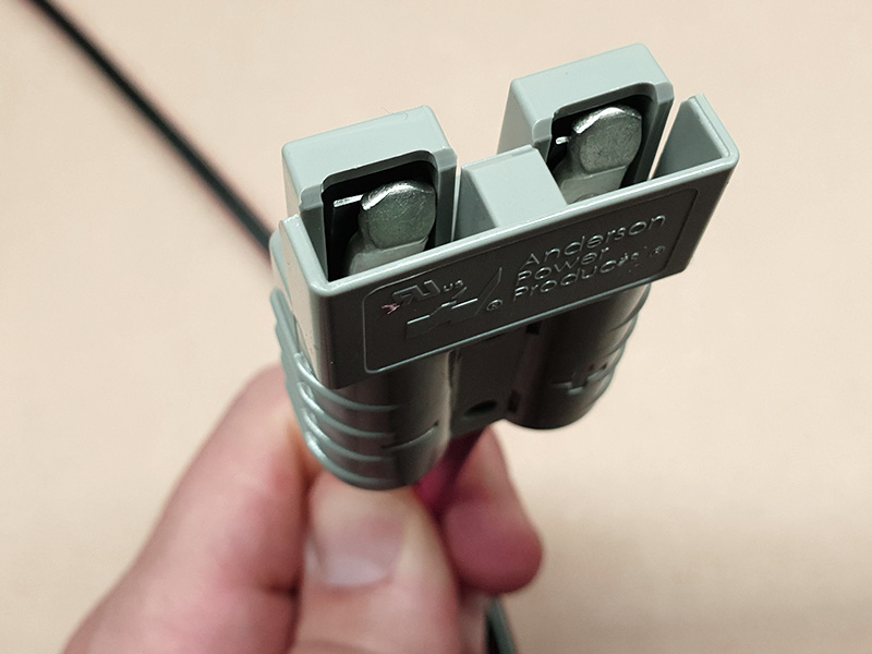
One of the most common questions Jaycar team members get asked about Anderson High Current connectors is: Which is the plug and which is the socket? The thing is, while Anderson High Current connectors look like a plug and socket at first glance, there is really only one connector. However, it is set up so that it is symmetrical and when rotated around, it connects with another one exactly the same!
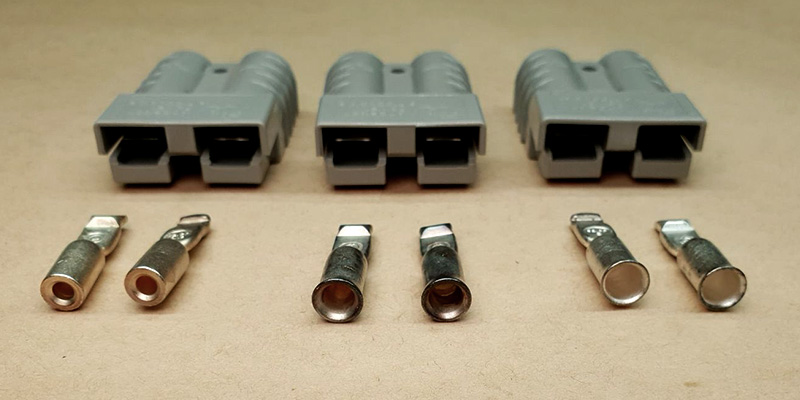
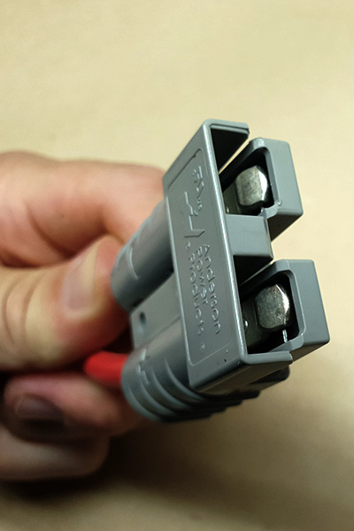
Inside an Anderson High Current connector are two contacts with a spring retainer behind each. This retainer both holds the contact into the connector, and applies spring pressure to ensure good contact. These flat spring steel retainers are visible from the front and back of an empty connector.
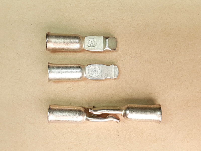
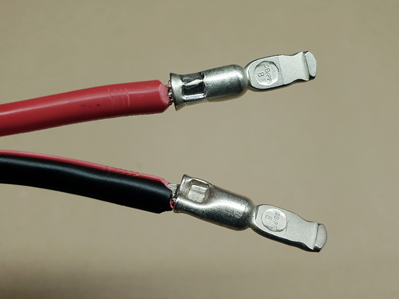
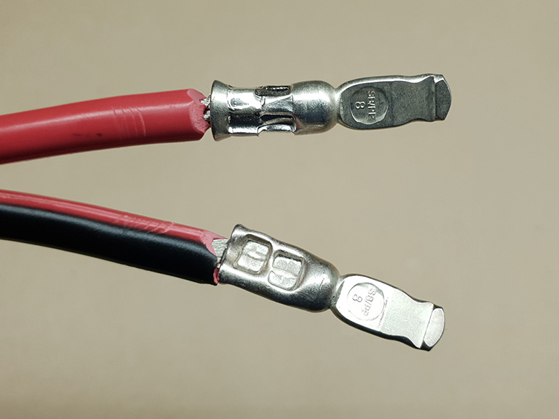
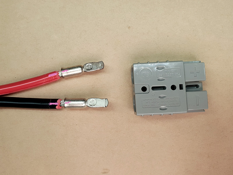
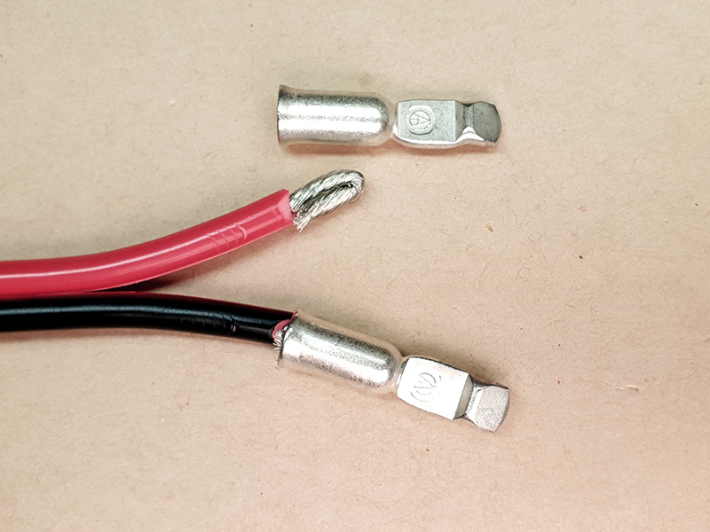
The contacts are also designed so that they work as both halves of a connection. The image shows two on its own at the top, one contact face up and one contact face down (showing the spring retainer latch), then two laid on the bench the way they would be inside two connectors that have been joined. Note that this represents only one side of the side-by-side configuration of an Anderson High Current connector.
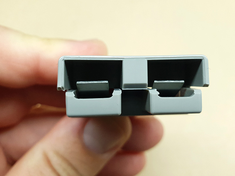
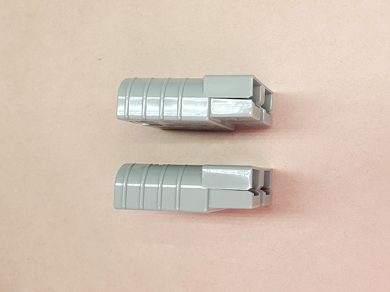
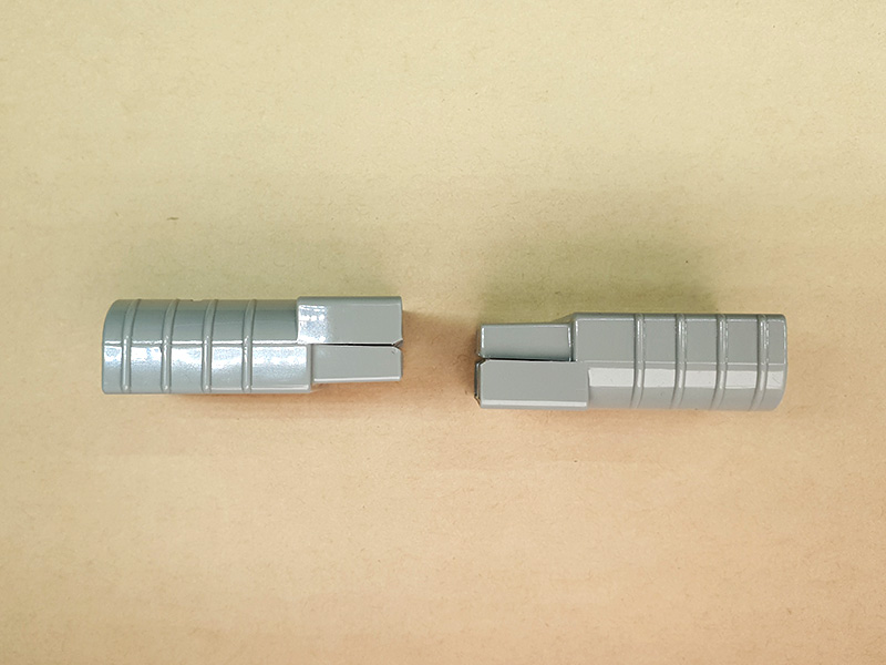
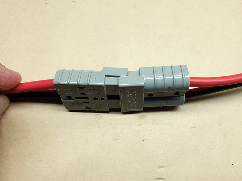
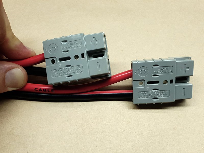
The housing for the Anderson High Current connector also has some points to note. Notice in this side-by-side view, we have two connectors arranged one over the other, then in the next photo, the same two connectors with one rotated 180° and facing the first one. Now, they are a connecting pair. Note the contacts are not fitted yet.
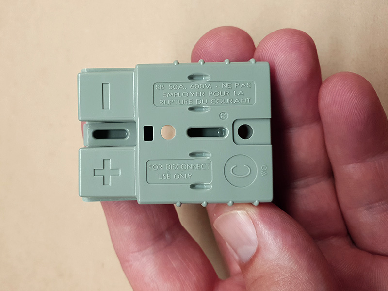
Finally, the connector housing has polarity marked on it. The + and - signs are moulded into the housing on the face that ends up hidden when two halves are connected. This is really important when you are inserting the contacts after making a wire join to them, when first assembling the connector. Getting this wrong can mean a lead that short-circuits a battery or feeds power the wrong way around to an accessory. In the first case, that can cause a fire and in the second case, that can destroy the appliance or accessory, or also start a fire! These are very safe to use so long as you take care and double-check everything!
Anderson High Current connectors come in a variety of sizes and choosing the right one is not based on the physical size of the connector suiting your needs. Instead, connectors should be chosen based on their current rating. Electricity can be likened to water flowing in a pipe. Voltage is the pressure the water is under. Current is the amount of water in litres per minute that is flowing. Anderson High Current connectors are always used on 12V systems, so the only factor is current. With water, to move more liquid per minute at the same pressure, a bigger pipe is needed. It's the same with electrical current, measured in Amperes which we call 'Amps' and represent with the upper case letter 'A'.
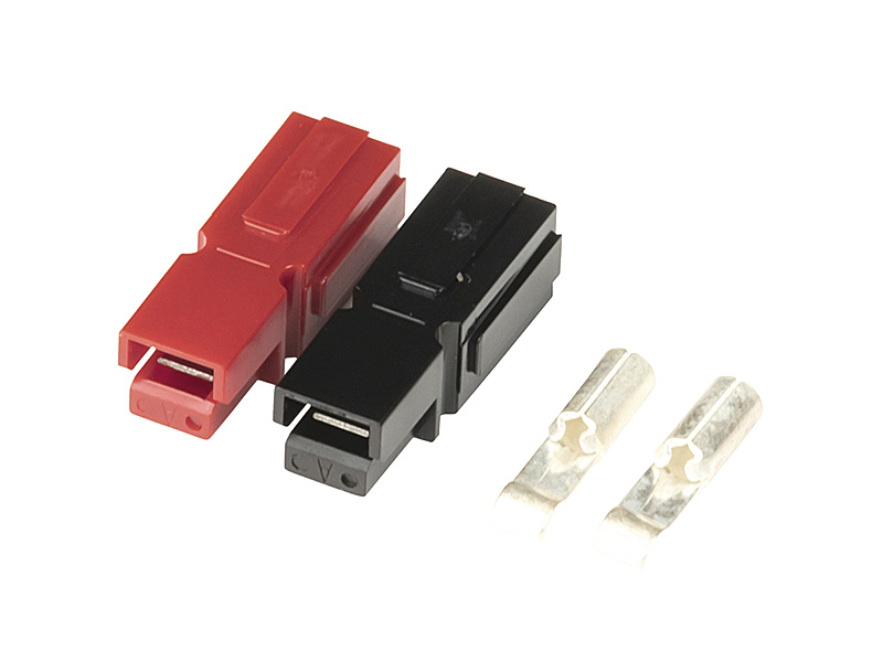
So, if you need to connect a winch that draws 40A, you will need an Anderson 50A High Current connector because that is the next standard size up and you always go up, not down. However, if you only need to connect a 5A load, you can get much smaller Anderson High Current connectors. Many of the smaller ones come as two halves with their own contact in each, which slot together to make a bigger connector.
Having said that, in many cases, an Anderson 50A High Current is used for smaller currents because it has become an industry standard. Just like at home on the garden tap, you can happily put an 18mm garden hose (the bigger domestic size) on your taps that are fed with 12mm pipes (the normal size) and everything works fine. However, also like with water, if you try to connect your 12mm garden hose to a fire truck's pump, it will split open. Using a 50A connector to pass, say, 70A will result in a lot of heat because the contacts (and wire) are too small to carry the current. In serious cases, this results in melting. In extreme cases, this will cause a fire. That's why there are Anderson High Current connectors around up to 175A.
So, in summary, while many people will only have seen the Anderson 50A High Current connector size, be aware that there are both smaller and bigger ones, and you can use a big connector on a small current but NEVER a small connector on a big current.
For the same reasons and more, choosing wire size is important, too. Because the Anderson 50A High Current is the most common size, but not all applications require 50A, the connectors come with contacts made for different wire sizes. Like the water in a pipe likeness from above, the size of a wire determines how much current it can carry. However, distance also plays a role. All metal resists the flow of electricity slightly, so over a long distance, and this reduces the voltage slightly for a given current. So, if you draw 50A through a 50A rated cable, but over 20m or so, the voltage at the end will be lower than at the start.
While there is no easy guide without lots of maths for us to suggest a wire size for a given length and current, just know that if you are going long distances, more than 5m or so sometimes, then you may or may not need a bigger wire size than for a short run. The best way to know for sure if you are going to be getting close to a given wire size's current limit is to ask your expert Jaycar team member for help.
While Anderson 50A High Current connectors are commonly made for 8G cable (8AWG, or American Wire Gauge), which is rated at 56A for 1m, there are also 6G and 10G wire sizes in the same connector body. 6G is larger than 8G, and 10G is smaller.
While no damage can be done by using a big wire on a small current, it can be a waste of money. There is no use running 50A wire across the length of your 4WD to run a fridge if the fridge draws 7A but happens to have an Anderson 50A High Current connector just because it's the standard. While it can be tricky to connect smaller wire to even the 10G contacts (see below), it may save you a lot of money and effort (smaller cable is easier to lay into small or narrow spaces).
There are two main options for attaching wire to an Anderson High Current connector contact. The first is soldering. For those unfamiliar with it, soldering uses heat to melt a special blend of metals which is quite soft, melts at a relatively low temperature (220°C) that is lower than any of the metals that make up the mixture if they were melted on their own, and is very electrically conductive.
However, soldering an Anderson High Current contact, and the wire size to suit, cannot be done as easily as soldering electronic components to a circuit board. It takes a lot of heat! Not a higher temperature necessarily (although up to a point, that helps), but lots of heat at once. Little circuit board soldering irons cannot pump the heat in fast enough before the massive amounts of metal in the wire carry it away. The solution is puddle soldering. This involves using a powerful soldering iron (often a gas one but not a direct gas flame) to heat the wire end quickly, and applying some solder to 'tin' the connection. Then, you heat the contact and fill the wire socket with solder to form a pool. You insert the tinned wire, let the heat of the pool melt the tinning and bond to the wire, and hold it all while it cools.
For the vast majority of people, including us, crimping is easier. This involves squashing the contact body in a certain way to squeeze the wire inside tightly. If done well, this is a great connection method that can stand up to the same demands as a solid soldered connection. If done poorly, crimps are a constant source of problems, heat, on and off connection, and even fire!
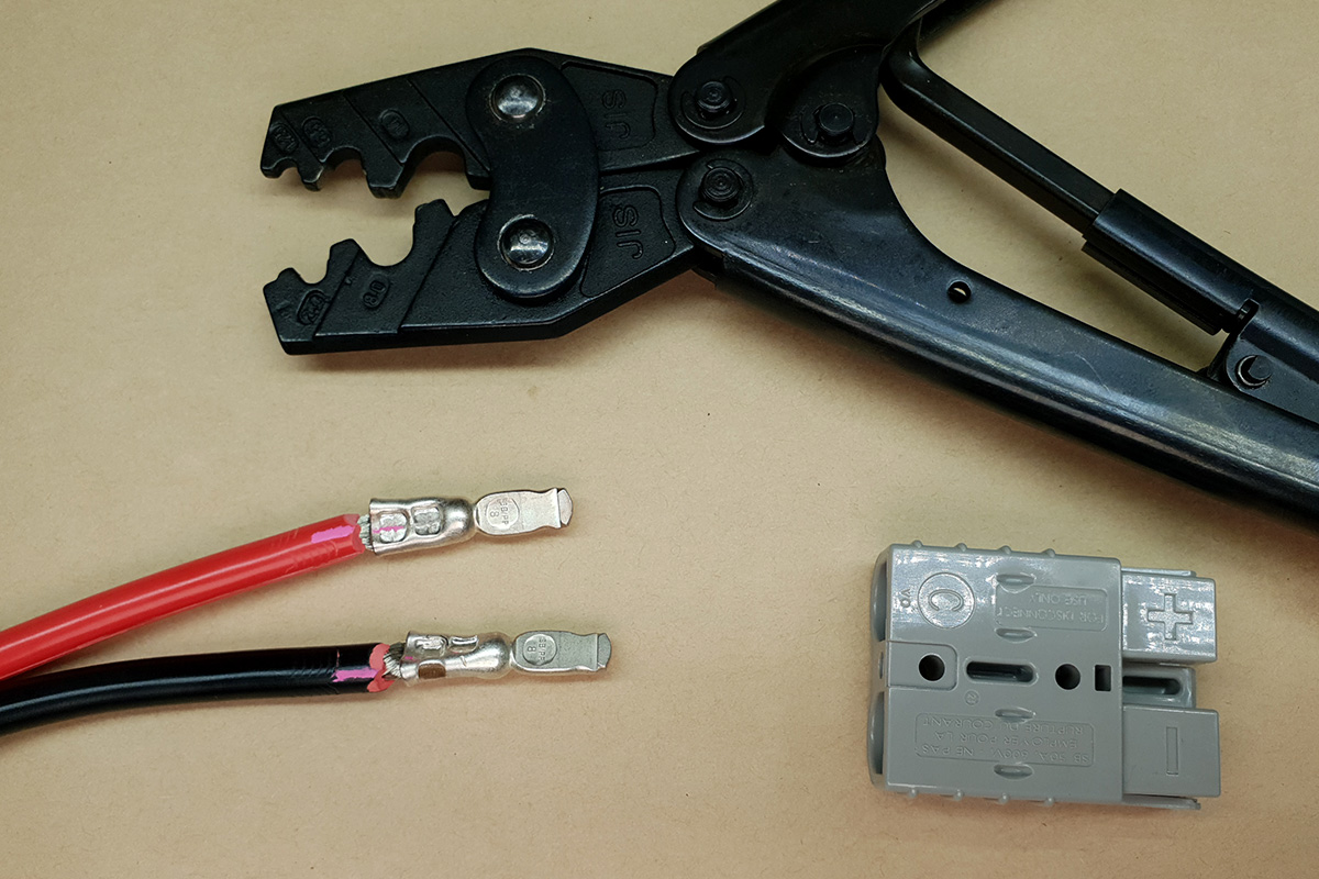
Having the right crimping tool is essential to make a good crimp. There are some that are ideal, and others which are totally unsuitable. Basically, those that are made for other types of connectors are not the right ones. The truth is a bit more complex.
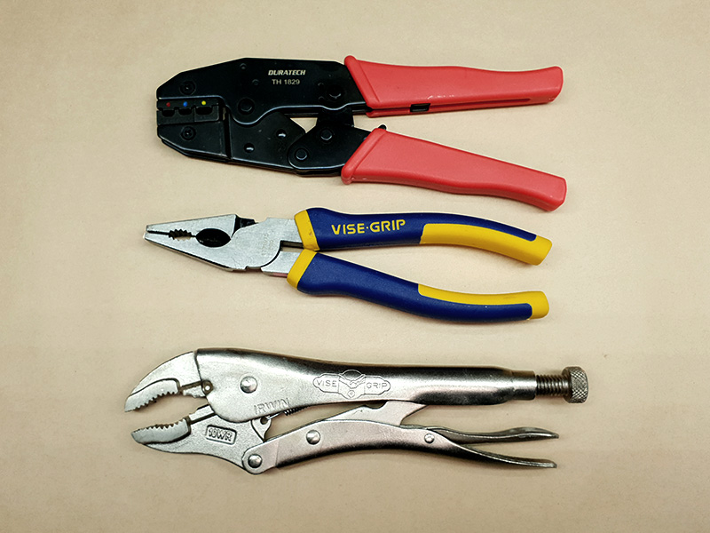
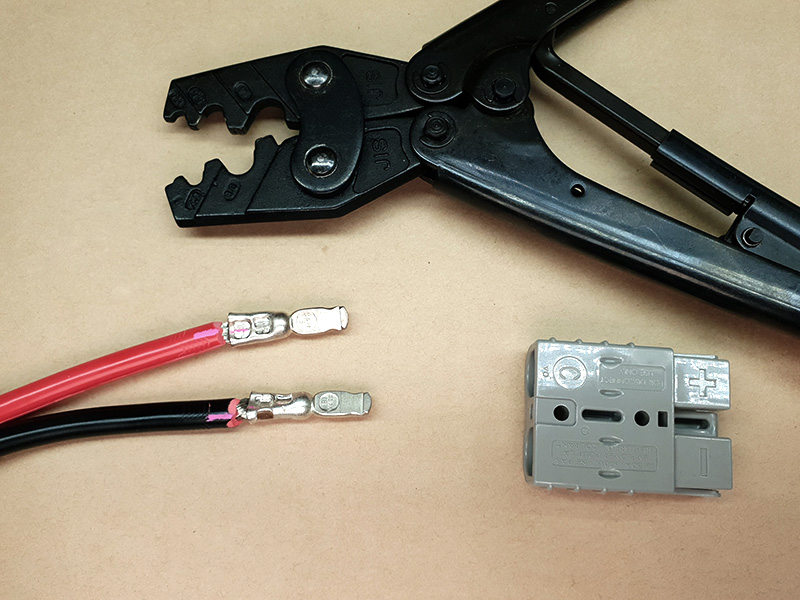
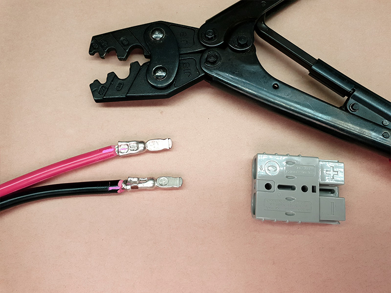
Pictured are some tools which are not suitable. The thin sheet metal type that has a wire cutter and several different types of crimp type in one tool are far too weak and the crimps far too small. They're ok for people who just do an occasional small crimp but we don’t even keep a pair in the workshop! Likewise, the stronger-looking one is probably strong enough to crimp an Anderson High Current connector, but the size of the crimp area is meant for the yellow, blue, and red insulated connectors and are far too small for an Anderson 50A High Current crimp. Note, never use vice grips, multi grips, or pliers! These produce a flattened crimp with no compression from the sides, and are not strong enough.
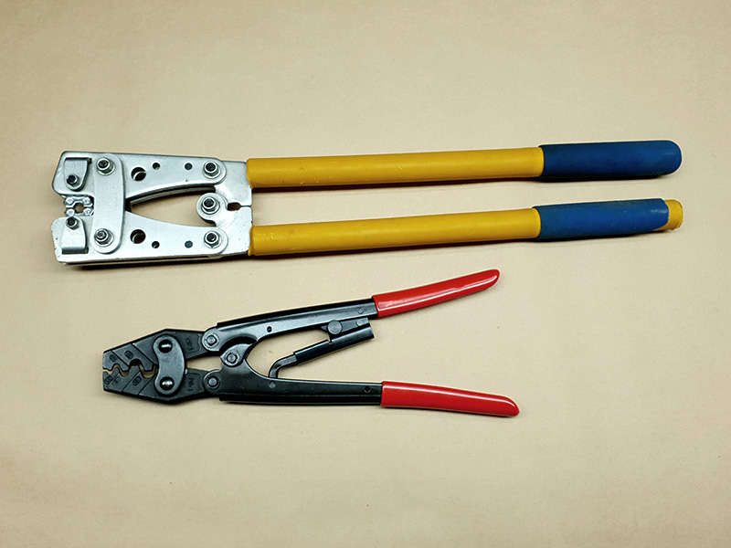
The correct tool needs to be strong enough to deform the contact, and have a hexagonal or u-shaped crimp area that is the right size. Too big, and it will not squash the contact enough. Too small, and it will pinch the sides and cause a total mess, not to mention possibly leaving sections of the contact with not enough crimp and others with too much! The ones in the picture are examples of the correct tools. Both have strong handles with lots of leverage. One uses hexagonal crimp dies, which rotate to find the correct size. The other uses u-shaped dies, with a matching smaller u-shape that pushes the centre of the connector. We will use both in the next section.
Making a good crimp involves good wire preparation, and the correct performance of the crimp itself. The key is to fill the socket area of the contact with enough wire that the crimp can firmly squeeze down. If the wire is too loose in the crimp socket, then no matter how well you perform the crimp, it will not be solid. The metal of the contact does not squash down infinitely. It is designed to only go so far.
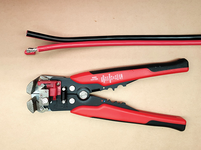
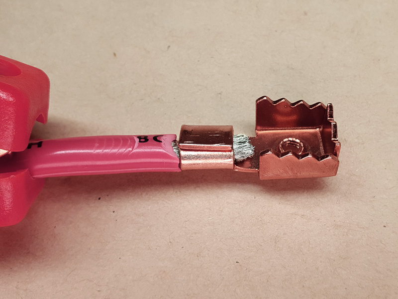
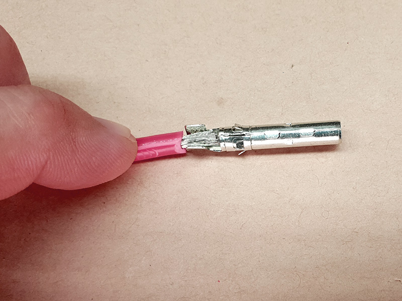
Firstly, strip some of the plastic insulation away from the end of the wire. The tool pictured here is an automatic wire stripper and will make your task much, much easier, especially if you need to do a few connections. However, a knife can be used if you are careful, or a pair of pliers if you already know how. Twist the strands of wire in the direction they are already twisted to neaten up the bundle and make it easier to work with.
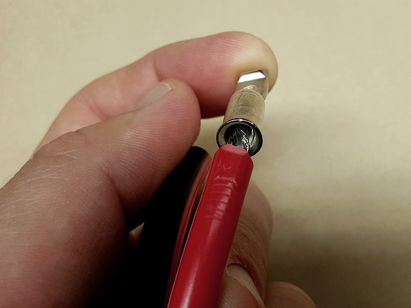
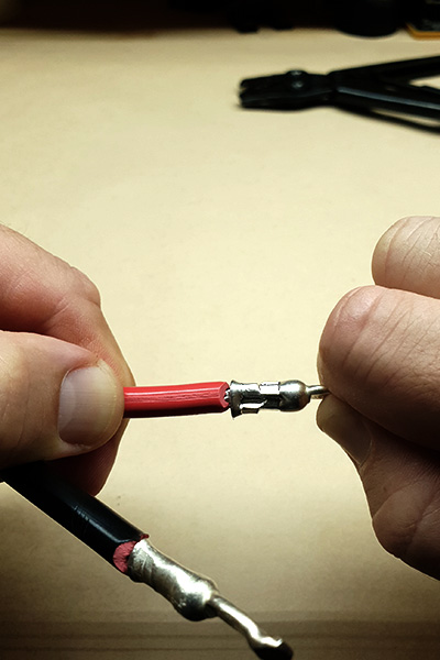
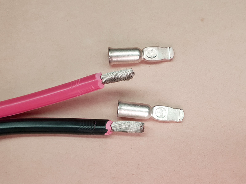
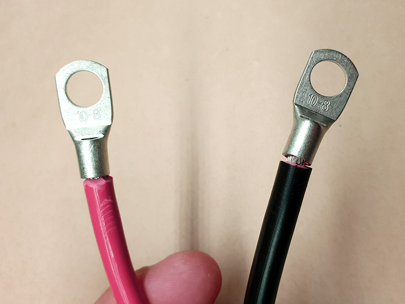
Next, determine how well your wire fits your contact. In the image, we have an Anderson 50A High Current connector with 8G wire taking up most of the space, but 12G wire swimming in it.
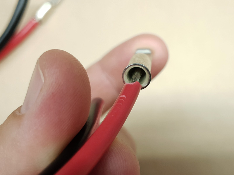
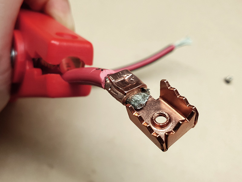
To make smaller wire work, you need to fold the wire over. Strip more of it and twist the strands to tighten and neaten the bundle. Fold it over in half, or three times, or more, to make the end of the wire bulkier. The aim is to fill the socket in the contact.
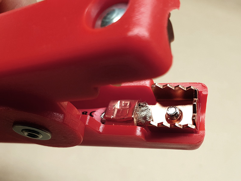
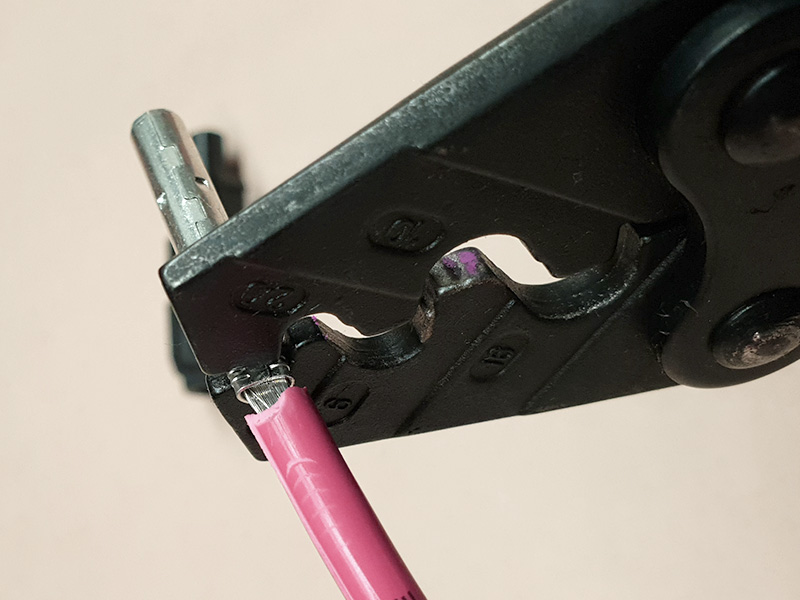
Only now can you crimp the wire. Position the contact into the jaws of the open crimp tool. Aim for the end of the contact first, closest to the wire. This is because with many crimp tools, you will need to crimp more than once up the length of the contact.
Squeeze down hard until the handles of the crimp tool are fully closed. You should see a hexagon that is visibly smaller than the contact was, or a deep u-shape, depending on tool type.
Move the crimp tool along the contact, away from the wire, and repeat. Do this again if necessary to crimp most of the contact area. Some crimp tools are wide enough to do this in a single crimp.
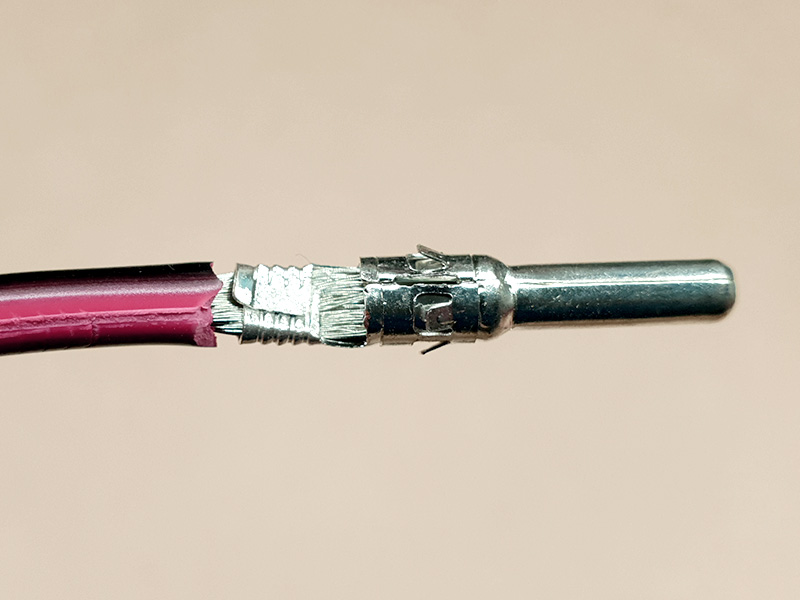
If done correctly, pulling on the end of the wire firmly but not roughly or with excessive force, should not move the wire at all.
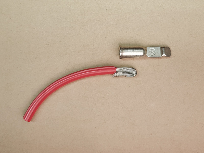
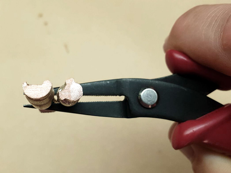
To demonstrate how the crimp looks inside, we cut open both a hexagonal and U shaped crimp. Note how densely the strands are packed.
The following demonstrations illustrate some of the more common types of Anderson High Current leads people wish to make. Be aware that there are variations of the connectors involved, especially eyelets! However, the general principle remains valid. We have used Anderson 50A High Current connectors because these are used in the majority of situations as discussed above. Most use 8G wire, but some, like the solar/MC4 lead, use smaller wire to suit the other connectors.
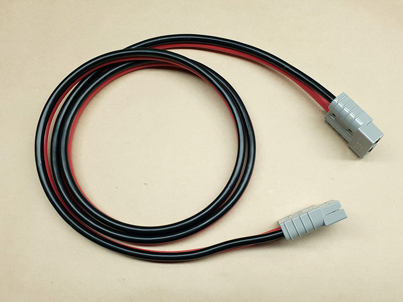
Anderson High Current Connector to Anderson High Current Connector leads can be used as both extensions, and for changing the size of a connector. For example, you may have a battery box fitted with Anderson 50A High Current connectors, but a small appliance with a smaller Anderson High Current connector. However, for this example, we are using Anderson 50A High Current connectors at each end, and 8G twin-core wire.
Prepare the wire by stripping enough insulation from the ends to fit neatly into the contact socket without leaving too much bare wire exposed. If in doubt, use a thin object like a toothpick to gauge the depth of the contact socket.

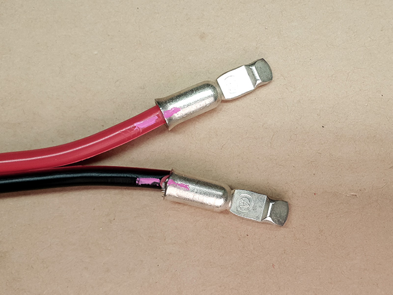
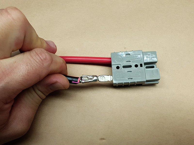
Then, slide on the contacts and align them so the contacts will sit comfortably in the housing with the correct polarity (red to + and black to -). Mark the position on the contact and wire with a marker, so that you can get it right again when you move the wire to crimp it.
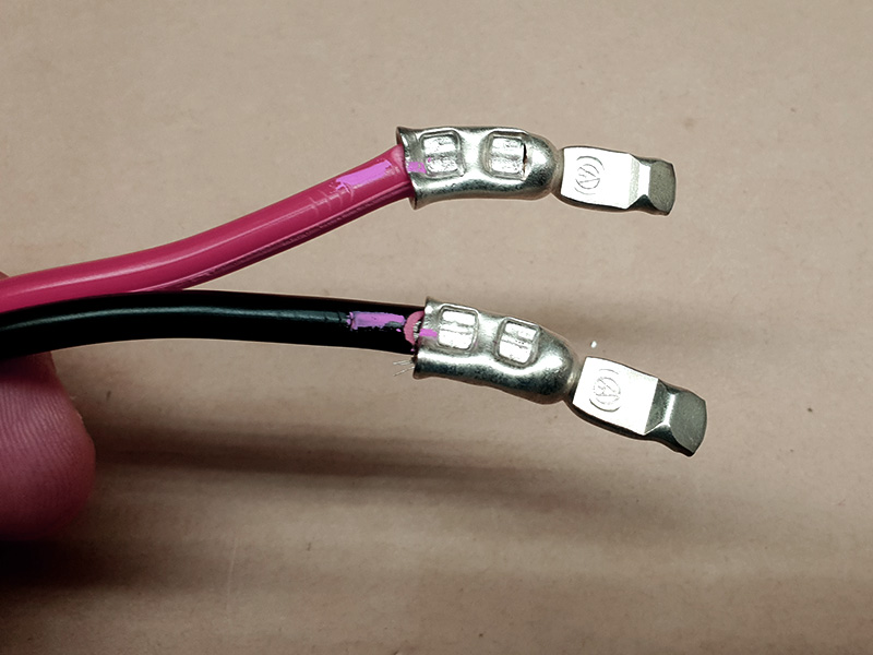
Crimp the contacts one at a time, taking care to keep the marks aligned. Crimp firmly and make sure the contacts cannot move.

Slide the contacts into the housing so that the retainer spring clips in behind the lug on the back of the contact. Pull back to make sure they do not move. Doing so may take some pressure to get the contacts up over the springs.

When you're done, the contacts sit on the springs with the lug underneath in front of the edge of the spring.
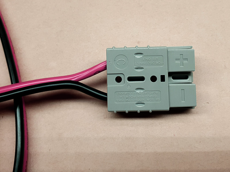
That's one end done! The other end is a repeat of the same steps, but you might need to turn the wire over to make sure the polarity stays correct. Once you have both ends crimped and inserted into the housings, bring the two connectors together and check that - aligns with -, and + aligns with +.
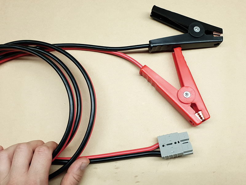
One of the common endings for an Anderson High Current lead is battery clips. This is often for attaching a solar panel to battery terminals, either for solar panels that have a charger built in, or for Lithium batteries that have a Battery Management System built in. It is also often used for taking temporary loads straight from a battery, such as a tyre inflation compressor.
Prepare the wire by stripping enough insulation from the ends to fit neatly into the contact socket without leaving too much bare wire exposed. If in doubt, use a thin object like a toothpick to gauge the depth of the contact socket.
Then, slide on the contacts and align them so the contacts will sit comfortably in the housing with the correct polarity (red to + and black to -). Mark the position on the contact and wire with a marker, so that you can get it right again when you move the wire to crimp it.
Crimp the contacts one at a time, taking care to keep the marks aligned. Crimp firmly and make sure the contacts cannot move.
Slide the contacts into the housing so that the retainer spring clips in behind the lug on the back of the contact. Pull back to make sure they do not move. Doing so may take some pressure to get the contacts up over the springs.
When you're done, the contacts sit on the springs with the lug underneath in front of the edge of the spring.

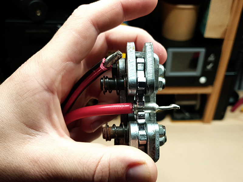
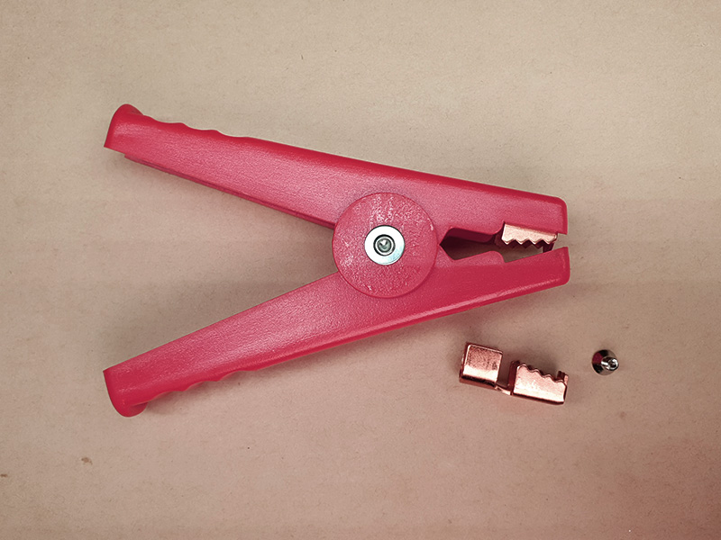
That's one end done! To connect to the battery clips, first have a good look at the clips you have. Some feature a screw terminal, others have a crimp fitting. These ones feature a crimp fitting, but of a different style. First, unscrew the jay section that has the crimp fitted to it. Slide the wire through the battery clip and bring it out the front.
Bare some of the wire by stripping back the insulation, and twist the bundle of strands to make it neat and tight. Lay it on the crimp section.
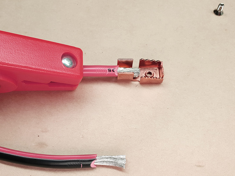
Use pliers or similar to fold one side of the crimp over, then the other down on top of it.
Ideally, fit the crimp into a hexagonal crimp tool and firmly squeeze it. However, your tool may not do this, especially if you have a U-shape style tool. Instead, you may need to squash very firmly with pliers or vice grips, ensuring the cable is very squashed.
Withdraw the wire to bring the crimped jaw back into the clip housing and screw it back into place.
That's one clip done! The other clip will be exactly the same, just a different colour to match the other wire. With both clips on, and the Anderson High Current connector on the other end, your lead is finished.
MC4 connectors are the ones commonly used for solar panel connections. You may need to make your own Anderson High Current to MC4 leads to connect solar panels to your auxiliary battery system, or to connect one to some DC-DC chargers. You might even be making custom charging cables for certain battery power station systems which use the MC4 on the opposite polarity to normal to try to make you buy their expensive adaptors! Also of note is that MC4 connectors usually suit a smaller wire size than we have been using so far. This demonstration is made with 12AWG cable.
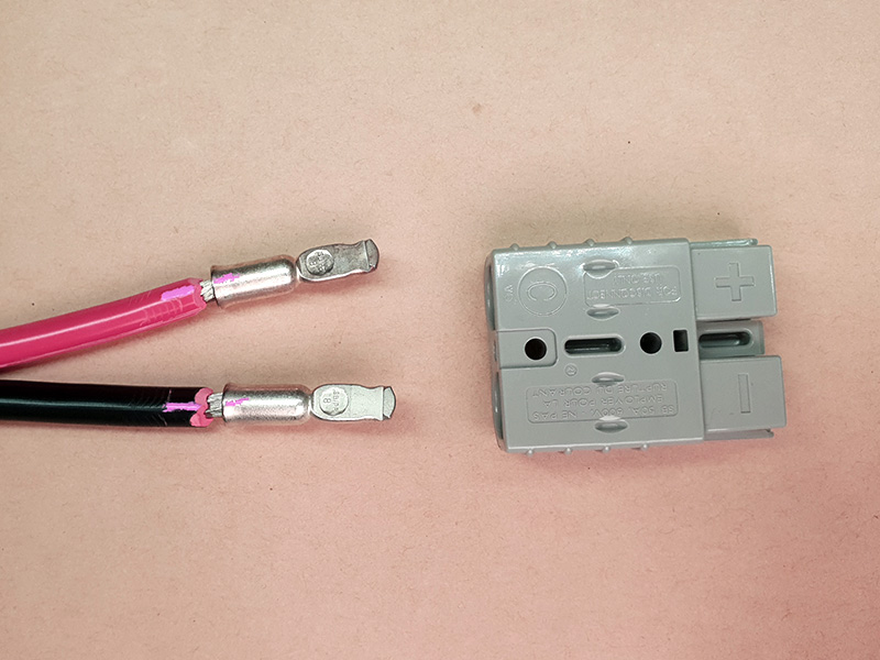
Prepare the wire by stripping enough insulation from the ends to fit neatly into the contact socket without leaving too much bare wire exposed. Bear in mind that with smaller wire, we have to fold the wire over on itself to get enough bulk to crimp. These are 8G Anderson 50A High Current connectors.
Then, slide on the contacts and align them so the contacts will sit comfortably in the housing with the correct polarity (red to + and black to -). Mark the position on the contact and wire with a marker, so that you can get it right again when you move the wire to crimp it.
Crimp the contacts one at a time, taking care to keep the marks aligned. Crimp firmly and make sure the contacts cannot move.
Slide the contacts into the housing so that the retainer spring clips in behind the lug on the back of the contact. Pull back to make sure they do not move. Doing so may take some pressure to get the contacts up over the springs.
When you're done, the contacts sit on the springs with the lug underneath in front of the edge of the spring.
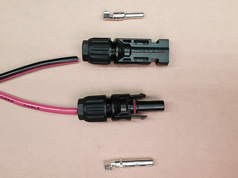
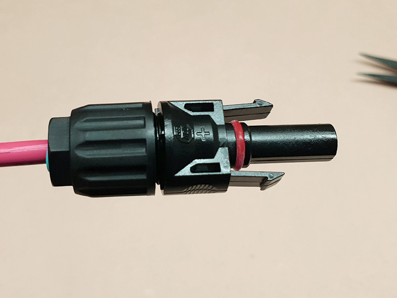
That's one end done! Now, the MC4 connectors. Check to see if you need normal or reverse polarity. Under normal circumstances, the plug MC4 connector (the one with the long narrow body extension poking out) is the positive, or red wire. The socket, the one that is thick all the way to the end, is the negative, or black wire. Note that the terminology varies between sources because some people refer to the body when describing plug and socket, while others refer to the contacts inside. The contact is actually hollow on the long thin body one, while the wide body one has the pin inside it! If in doubt, check this picture:
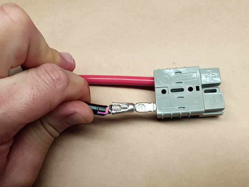
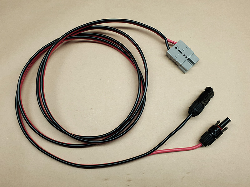
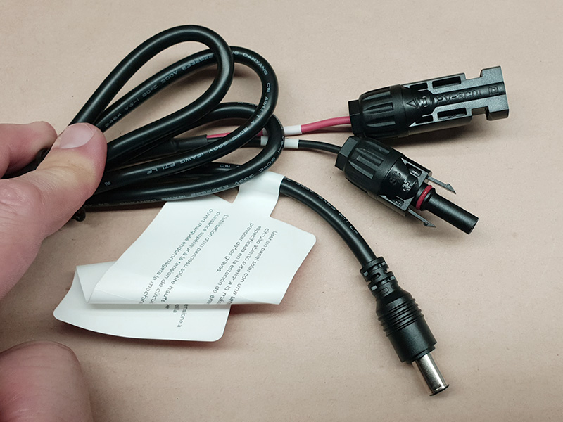
Some brand-name and off-brand systems, like some battery power stations, have their own way of using these connectors, in reverse. In that case, the long narrow body is negative, or black, while the wider body is positive, or red. This battery power station solar charging lead is an example. If you look closely, you can even see the + and - moulded into the plug and socket bodies being on the wrong colour wire!
Once you know which polarity you need, take out the contact from one of the connector packets. Leave the other sealed to avoid confusion. Strip the relevant wire of enough insulation to sit in the crimp section. This one is the plug being used in normal polarity, so on the positive red wire.
Use pliers or similar to fold one side of the crimp over, then the other down on top of it. Firmly crimp the contact with the appropriate tool. We used the smaller U-shape section on our crimp tool for this side, and tried the smaller hexagonal crimp die on the other contact further on. Both worked.
Once the crimp is firm and you have checked it by pulling firmly but gently on it, undo the nut from the back of the housing and remove the rubber seal. Slide both onto the wire over the contact.
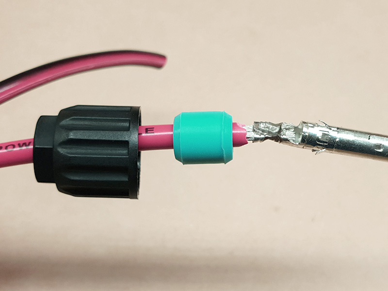
Slide the contact into the back of the housing and as far forward as it will go. You should hear a faint click as it seats home. You may need to push with small long-nose pliers. Then, slide up the seal and screw the nut home firmly.
With one MC4 connector assembled so that the contacts cannot get mixed up, you can repeat the process with the other. This one is the socket going on the black negative wire for normal use.
Assembly is the same for the socket: Slide the contact into the housing until it clicks. That's it, your cable is made!
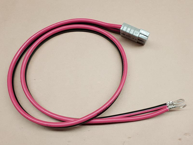
Eyelets are a common connection for battery terminals, fuse blocks, and other similar situations. They vary wildly in both wire size and eye size. Some have big eyes for large battery terminal bolts but small wire sizes, and sometimes you can get a large wire size with a comparatively small eye. The eye size is determined by the bolt size you want to attach to, and the wire size by the current you need to draw and the cable that will suit that. For this demonstration, we are using an Anderson 50A High Current connector with 8G wire, and 8mm battery terminal bolt size eyelets.
To make the Anderson High Current end:
- Prepare the wire by stripping enough insulation from the ends to fit neatly into the contact socket without leaving too much bare wire exposed. If in doubt, use a thin object like a toothpick to gauge the depth of the contact socket.
- Then, slide on the contacts and align them so the contacts will sit comfortably in the housing with the correct polarity (red to + and black to -). Mark the position on the contact and wire with a marker, so that you can get it right again when you move the wire to crimp it.
.jpg?branch=prod)
- Crimp the contacts one at a time, taking care to keep the marks aligned. Crimp firmly and make sure the contacts cannot move.
- Slide the contacts into the housing so that the retainer spring clips in behind the lug on the back of the contact. Pull back to make sure they do not move. Doing so may take some pressure to get the contacts up over the springs.
- When you're done, the contacts sit on the springs with the lug underneath in front of the edge of the spring.

That's one end completed!
To make the eyelet end:
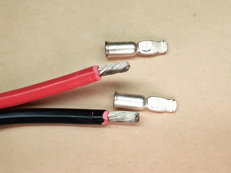
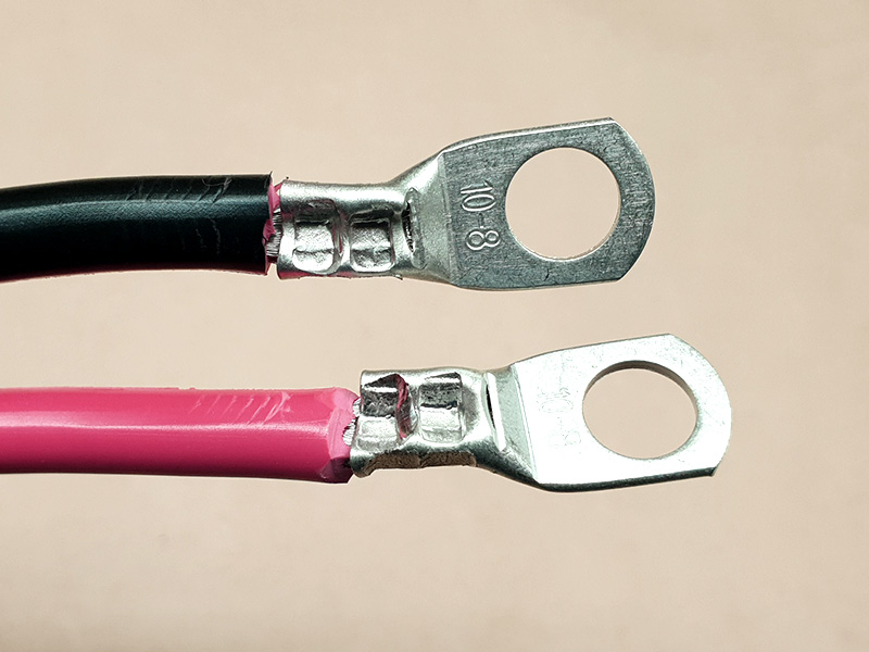
- Bare enough wire to fit into the crimp end of your chosen eyelet. Your wire size may dictate that you fold over your wire once or twice to give enough bulk for a firm fit. The eyelets we have here are of the insulated type, and only just fit the 8G cable if you twist it firmly.
- These eyelets need the appropriate crimp tool, meant for colour-coded nylon-jacketed insulated connectors. However, your eyelets may need a different crimp tool, such as those we have featured previously. Crimp firmly then check the connection by pulling gently but firmly backwards.
Once you repeat the process for the other wire, your lead is finished!
One of the best ways in which you can improve your connections to exposed connectors like eyelets is to use heatshrink. This is a special plastic tubing which shrinks when heated above 125°C. There are two flavours: Basic heatshrink is a 2:1 shrink, which means it shrinks to half of whatever it starts at. So, 5mm heatshrink in 2:1 will shrink to 2.5mm. This kind of heatshrink comes in the most sizes and a choice of colours.
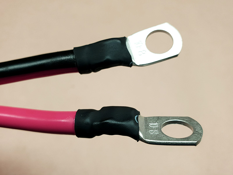
The other variety is 4:1 Glue Lined heatshrink, also known as double walled heatshrink. This product shrinks to one quarter (1/4) of whatever it started at. So, 12mm 4:1 dual wall heatshrink will shrink to 3mm. Better still the lining (the second wall) is a heat-sensitive glue. When heated to shrink temperature, it melts and floods the joint with glue. This seals it against moisture and bonds the heatshrink to it, too. It is very strong and mostly waterproof, although water can wick up into it if there are crevices in the surface that are not sealed well. We added 4:1 shrink after making our eyelet lead above, to cover the connection and help add strength. Being 4:1, we can fit it over the eyelets and still have it shrink well onto the wire.
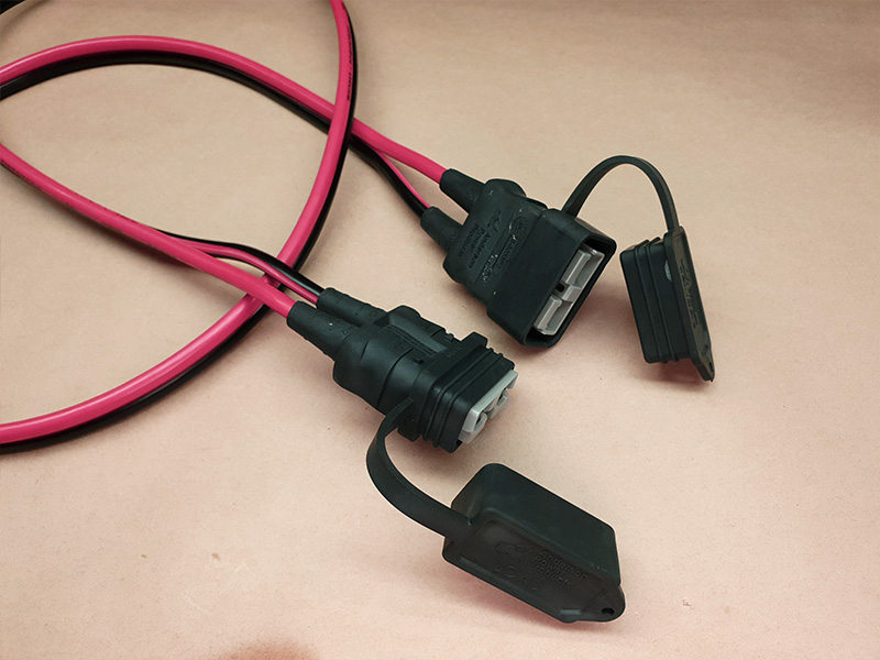
The other useful item relates to the Anderson High Current connectors themselves. These rubber covers are available in both plug and socket halves. While the Anderson High Current connectors are identical, the rubber covers are not. One fits inside the other to make a waterproof seal. They must be applied before the connector is assembled but they can be retrofitted- if you can successfully depress the spring retainer in the Anderson High Current connector and release the contact! The rubber boot will slide over the contact. We applied these two to our Anderson High Current to Anderson High Current lead from earlier.
Similar projects you may be interested in
.jpg?branch=prod&format=webp&width=428)