Progress Bar

Skip to main content

Jaycar
...

IR Helper

IR Helper

Difficulty
TEST & TOOLS

Summary

The main role of the IR Helper is to send IR signals automatically, so you don’t have to juggle multiple IR remote controls. Our prototype can do this in a couple of ways, but since it is programmed using the Arduino IDE, it is easy to extend and adapt.

You will need some Arduino knowledge, though, since you will have to change our prototype sketch to suit your equipment and its IR codes.

The IR Helper can be programmed to send a signal when it is powered on. Many devices like TVs have USB ports, so you can simply plug the IR Helper in, and it will power on when the TV does and send out the signals it’s programmed to generate.

The IR Helper can also respond to IR commands and perform extra actions by sending further signals to other devices. For example, the IR Helper could detect the TV being switched on remotely and then turn on a receiver, amplifier, DVD player, or all three!

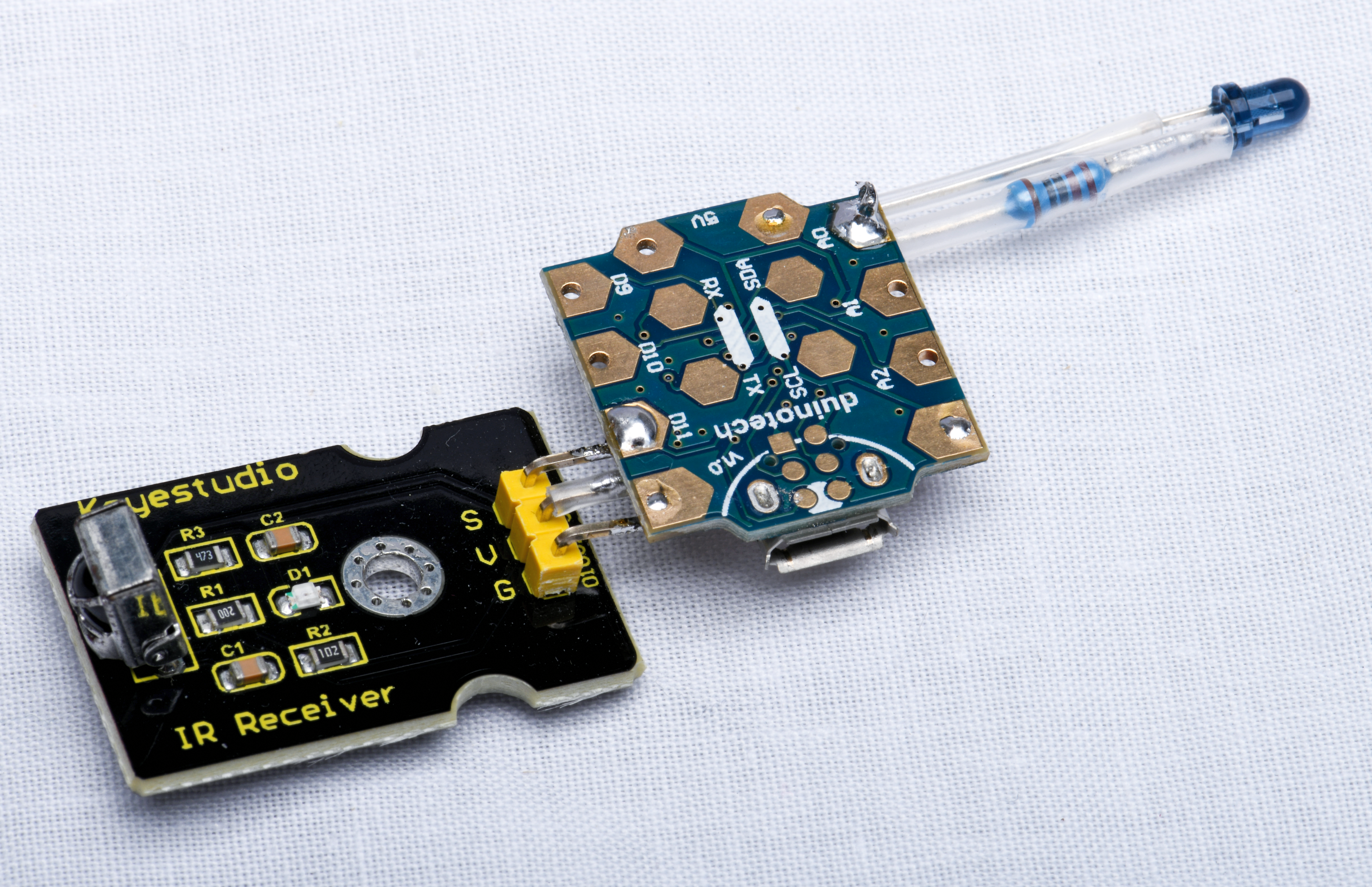
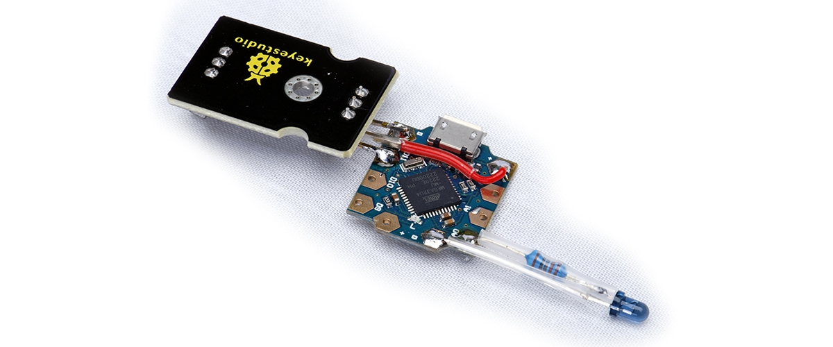
From the photos, you can see that the IR Helper has simple hardware. It uses two main modules: a small microcontroller module and an IR receiver module. We have used a module rather than a simple IR receiver because of its handy onboard LED indicator; it is also slightly cheaper.

An IR emitter LED is included so that the IR Helper can transmit as well as receive IR signals. The main processor is a compact Leonardo Tiny board with a USB interface. The USB interface is used to display received codes for testing, among other things.

We published an article in the August 2018 issue titled “Turn any PC into a media centre – with remote control!” (siliconchip.au/Article/11195). These two projects use very similar hardware, so you might be interested in reading the earlier article to see what else can be done with this basic combination of parts.

Materials Required

1Leonardo Tiny Atmega32U4 Main BoardXC4431
1Duinotech Arduino Compatible Infrared Receiver ModuleXC4427
13mm Infrared Emitting DiodeZD1946
1220 Ohm 0.5 Watt Metal Film Resistors - Pack of 8RR0556
1Red Flexible Light Duty Hook-up Wire - Sold per metreWH3010
15.0mm Clear Heatshrink TubingWH5553

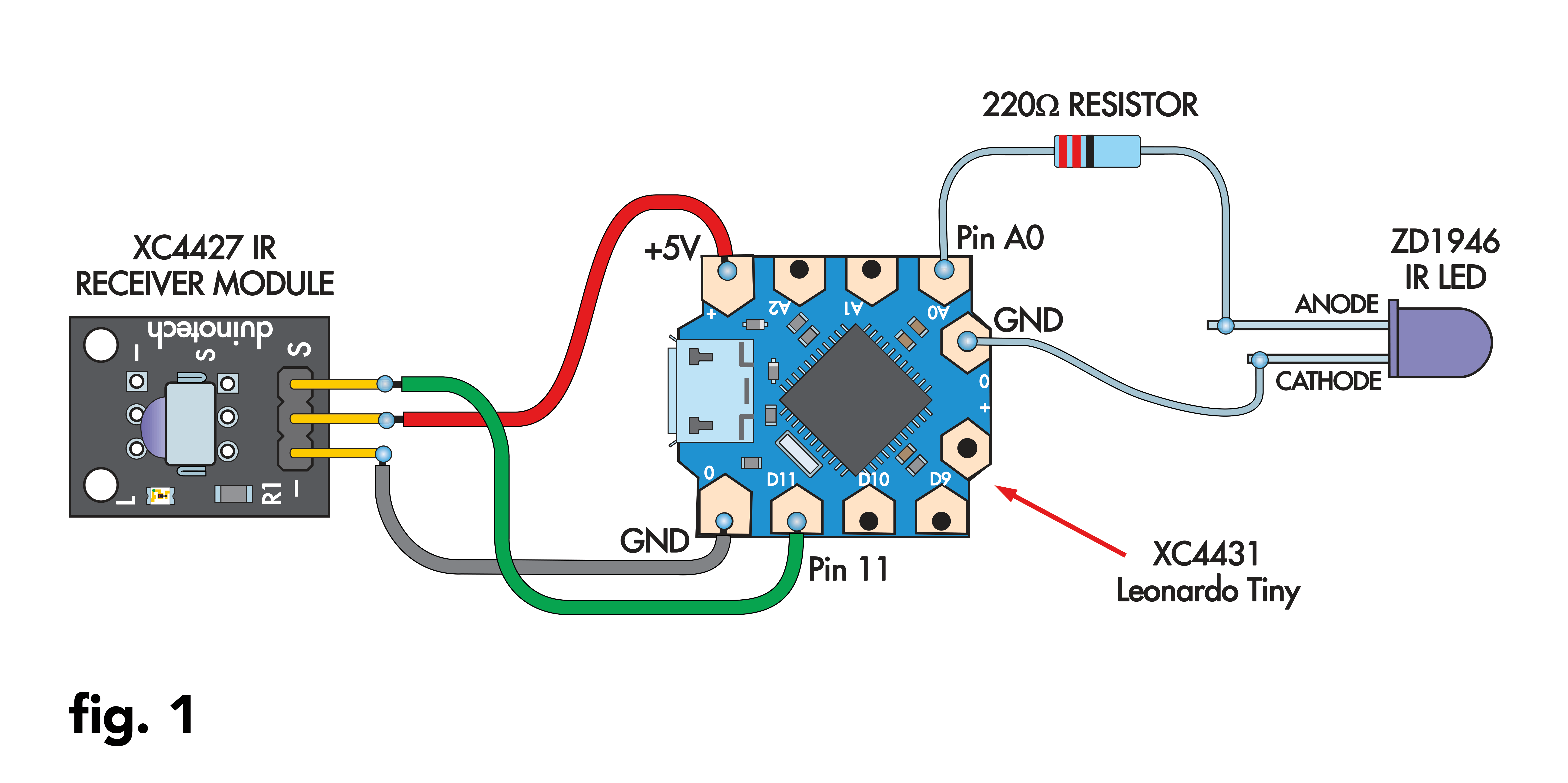
Fig 1 is the wiring diagram. We assembled our prototype by soldering the parts to the Leonardo Tiny board, using heatshrink tubing to protect the exposed leads where necessary. You could also use a full-sized Leonardo board if you wanted to.

fig1.png

If you have the Arduino Beetle board from the 2018 article, you could add the IR Transmitter LED, updating the hardware to suit this article, since both projects use the same pin for the IR receiver.

The IR Receiver Module incorporates one LED that illuminates when the IR receiver chip sees a valid, modulated signal. The S pin of the module goes low at the same time, signaling to the processor in the Leonardo Tiny that a signal has been received.

The Leonardo Tiny sends an IR signal by driving its A0 pin high, sending current through the IR transmitter LED. The pin does not have a lot of drive capability, but it’s enough for transmitting commands over short distances.

The IR LED in your handheld IR remote control will be driven much harder than the one in the IR Helper, but we expect that most readers will situate their IR Helper near the devices it is transmitting to. You can see that the IR receiver and transmitter are on opposite sides to facilitate this.

Solder the short length of red wire to the middle pin of the IR Receiver module, then cover the exposed parts of the pin and wire with a few centimetres of heatshrink tubing and shrink it into place. Solder the two outer pins of the module to the D11 and GND (-) pins of the Leonardo Tiny, as shown in the photos. Note that the module has to be upside-down for this to happen.

Next, solder the other end of the red wire to the 5V pad on the other side of the Leonardo Tiny.

Prepare the LED by cutting the longer anode lead to around 5mm. Cut one of the resistor’s leads to a similar length. Solder the two cut leads together, then use the heatshrink tubing to cover most of the LED’s leads separately.

This LED assembly can now be powered directly from a DC supply. You could use this idea on a breadboard or similar to add LEDs without needing to wire up separate resistors.

Now solder the exposed ends of the LED assembly to the A0 and GND pins of the Leonardo Tiny. You should be able to re-check the polarity by observing that the side of the LED with the flat edge connects to GND.

You can do a quick test by applying power and aiming a signal from an IR remote control at the receiver module. Its indicator LED should flicker while it is receiving a valid IR remote control signal.

JMP010_bot.png

You can download the Arduino sketch for this project: siliconchip.au/Shop/6/450

If you don’t already have it, download and install the Arduino IDE from www.arduino.cc/en/software

The sketch uses the “irremote” library. This library contains just about everything you need to send and receive IR signals for all manner of devices. To install it, search for “irremote” in the Arduino Library Manager and click the install button when you find it. We used version 4.3.1 of the library.

Then open and upload the IR_HELPER sketch. You will need to customise your sketch to work with your devices, but this is made easier since the prototype sketch will also show received codes on the Serial Monitor, allowing you to find the correct protocol and codes for customisation.

Screen 1 shows the typical result when two different buttons on the same remote control are pressed. Note how the sketch even displays the recommended Arduino code. We used three for the <numberOfRepeats>, but you could try increasing that if you find that codes are not being received.

Press the button you wish to emulate and check its code using the sketch, then copy it to the triggeredAction() function of the sketch and upload it again. You can then check whether the transmitter works by typing ‘t’ into the serial monitor.

The prototype sketch also sends this code whenever it sees a code matching the RX_ADDRESS and RX_COMMAND values. The prototype sketch will also run the powerOnAction() function every time it is powered on; you can add another IrSender command to that function if needed.

You would use this feature by plugging the IR Helper into the USB port of a device like a TV, so that when it is switched on, the powerOnAction() is run. Since many remote controls have a toggle action power button (i.e., pressing power can both switch the device on and off), this can be a good way to distinguish an ‘on’ action from an ‘off’ action.

From here, you should be able to see what changes you need to make to fit the sketch to your situation. You could also add other sensors to automate other functions. For example, you could rig up a light or motion sensor to switch on a lamp that has an IR remote control when it gets dark or movement is detected.

The IR Helper could also be used to add IR remote controls to devices that do not have it by wiring up a relay module to the Leonardo board to switch things on or off upon receipt of certain commands.

This article appeared in the May 2024 issue of Silicon Chip Magazine. Check out their website for other project ideas: https://www.siliconchip.com.au/

Similar projects you may be interested in

TEST & TOOLS
Service Aids - More Than You Think!
Difficulty

thumbnail
TEST & TOOLS
Stroboscope and Tachometer
Difficulty

TEST & TOOLS
How to extend HDMI signals to a different room
Difficulty

Installing and Setting Up the XC0440 Weather Station
TEST & TOOLS
Installing and Setting Up The XC0440 Weather Station
Difficulty