Progress Bar

Skip to main content

Jaycar
...

Revive your Arduino - ISP Programming

Revive your Arduino - ISP Programming

Difficulty
Test & Tools

Summary

A handy tool to have in your Arduino Kit is an ISP programmer. Aside from giving you a faster way of programming your Arduino Boards, an ISP programmer can also be used to reprogram a faulty bootloader (which may be preventing sketches from being uploaded), or even install a new bootloader with new features. Programming with ISP bypasses the bootloader, so it might allow you to squeeze a few more bytes of program storage into your sketch.

Alternatively, if you're looking a branching out away from prototyping with Arduino boards, and want to use a standalone IC like the ATMega 328P, you can use ISP instead of designing a USB-serial converter into your circuit.

You might not know it, but the USB-Serial converter IC on Uno and Mega is actually a ATMega16u2- the smaller brother of the ATMega32u4 on the Leonardo board, and this can be reprogrammed by ISP too (but be careful, as you might accidentally disable its USB-serial function).

Because all the Arduino boards have a 6-pin ISP header, we'll also need a 10-pin to 6-pin adaptor to connect to the 10-pin connector on the ISP programmer.

Materials Required

1ATMEGA328P MCU IC with Arduino UNO Bootloader and 16MHz CrystalZZ8727
1Arduino Compatible Breadboard with 400 Tie PointsPB8820
1150mm Plug to Plug Jumper Leads - 40 PieceWC6024
1Duinotech Arduino Compatible AVR ISP 10pin to 6pin AdaptorXC4613
1Duinotech ISP Programmer for Arduino and AVRXC4627
110k Ohm 0.5 Watt Metal Film Resistors - Pack of 8RR0596

So what is ISP programming? Unlike the USB-serial method used for most Arduino boards (and this method depends on extra components on the Arduino board), ISP is actually something that is included in the ATMega IC, which means it works at a lower level, and can even be run on bare ATMega IC's. If you're more interested in how ISP works, it's documented in the Atmega 328P datasheet, but briefly, the ISP programmer actually uses SPI as its communication protocol. You'll see that there's the normal SCK, MOSI and MISO pins on the adaptor, but instead of the CS pin, it uses the RST pin- so any time the ATMega IC is in reset, it is actually ready to accept commands via ISP. The SPI protocol means that communication can be faster than the serial protocol normally used for uploading.

For the most part, you should just be able to plug the programmer into your computer and plug the other end into the ISP header on your Arduino board, but there are some settings that can be changed by moving jumpers on the programmer:

JP1 allows the ATMega IC on the programmer to be reprogrammed when a jumper is fitted. Note that this will require a second programmer. We haven't ever found the need to use this option.

JP2 selects the voltage level that is supplied to the board being programmed. This can be 5V (which is fine for most boards like the Uno, Nano, Mega and Leonardo) or 3.3V (which suits the Lilypad). The jumper can also be left off completely, if your board already has its own power supply and doesn't need external power.

JP3 can have a jumper fitted to slow down the clock (note that might also need to install header pins here as well). If you find that programming just isn't working, slowing down the clock may help, especially if the ATMega IC has been set to use a very low processor frequency. We've sometimes had to use this option to fix incorrectly programmed devices.

Unlike the Arduino boards, the drivers for the ISP programmer are not included with the Arduino IDE, but can be downloaded from the downloads page. Plug the ISP Programmer into a USB port and try installing the drivers. You might find that later versions of Windows might prevent installation due to the drivers not being digitally signed. You can install unsigned drivers by following these instructions:

  • 1. Click the Start menu and select Settings.

  • 2. Click Update and Security.

  • 3. Click on Recovery.

  • 4. Click Restart now under Advanced Startup.

  • 5. Click Troubleshoot.

  • 6. Click Advanced options.

  • 7. Click Startup Settings.

  • 8. Click on Restart.

  • 9. When the computer restarts, press 7.

The computer will now allow unsigned drivers to be installed.

When the ISP programmer is properly installed, it should appear in Device Manager like this:

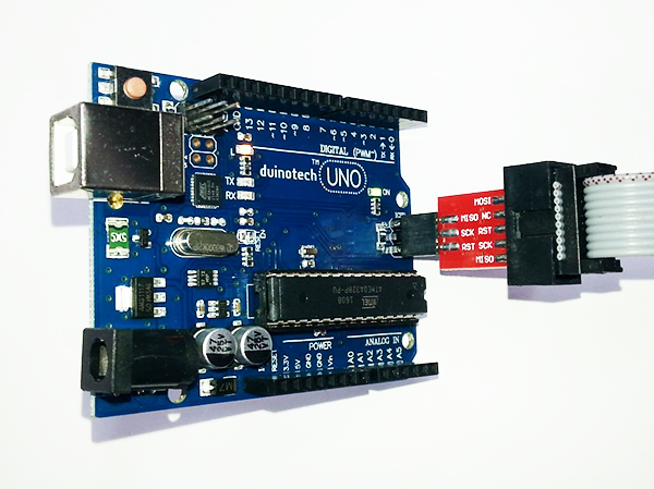
If you are familiar with the Arduino IDE it's probably the easiest way to use the programmer- there are also standalone programs. With the ISP Programmer plugged into the computer, plug the 6-pin end of the adaptor into an Arduino Board- I've got an Uno. Note that the MISO pin is pin 1, and should line up with the locating dot, if it is present. If the power light on the Arduino board doesn't light up straight away, unplug it, as it might be the wrong way around.

Also be careful that you don't connect to the second ISP header near the USB socket (this is only present on the Uno and Mega). This is actually to program the second IC on the board (the one that handles USB-Serial conversion), and if this IC is programmed wrong, you might not have any communication at all.

To use the Programmer, open up your sketch and select your board as per normal. Under Tools, select Programmer>USBasp, then to upload via ISP, press Ctrl-Shift-U instead of Ctrl-U.

You might get a warning about needing a usbasp firmware update, but if the sketch uploads, everything will be fine.

If you do get an error message, check that the correct board type is selected (the error message should suggest that). If the board is correct, double check the connections.

Most of the time, the Programmer can also be used to change or repair a bootloader (that's a small program on the Arduino board that the Arduino IDE normally uses to upload sketches). Especially if the ATMega IC has been programmed to only allow parallel programming, reprogramming with the ISP Programmer may not be possible. Note that this will erase any sketch code on the board.

Uploading a new bootloader is quite easy- connect the board as above, then select the board type, and choose Tools>Burn Bootloader- you should get a message saying 'Done burning bootloader'. The first thing to try if it fails is to enable the slow clock jumper JP3. If this fails, your ATMega IC may be damaged or have settings that prevent ISP programming.

A perfect use for the ISP programmer is building your own prototypes- for example if you have a circuit working with an Uno, but now you want to make it smaller or more power efficient, you can ditch the USB-serial converter, and use an ISP programmer to program the board. The following circuit uses these parts:

Wire the ATMega 328 IC and crystal as follows:

Pin Name

Pin Number

Connection

VCC

7

5V supply

AVCC

20

5V supply

GND (x2)

8 and 22

Ground connection

RST

1

Connect to VCC pin via 10K (approx) resistor

X1

9

Crystal

X2

10

Crystal

Then connect the ISP 10-pin to 6-pin adaptor:

IC Pin Name

IC Pin Number

ISP Connection

VCC and AVCC

7 and 20

VCC

GND (x2)

8 and 22

GND

RST

1

RST

D11 (MOSI)

17

MOSI

D12 (MISO)

18

MISO

D13 (SCK)

19

SCK

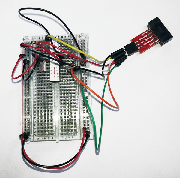
Ours looks like this:

Note that the 10-pin to 6-pin adaptor allows the ISP to be unplugged from the circuit if necessary.

Plug the ISP programmer into the adaptor, and then, the IC can be programmed via ISP as though it were an Uno board. To test if it's working, you could fit an LED between D13 and GND, then upload the 'Blink' sketch. Apart from the lack of a 5V regulator and the USB-Serial converter, it's almost the same as an Uno.

If you do want to run a circuit like this away from your computer and you don't have a USB power supply available, the Uno is happy with any voltage from 4.0V to 5.5V, so 3xAA batteries will work just fine.

Of course the above circuit isn't much good by itself, but if you are looking at creating a battery powered application, it's a good place to start. This circuit is a lot less power hungry because it's not running unnecessary components like the USB-Serial converter. We're working on a battery powered project, so soon you'll be able to see just how much power you can save with a minimal circuit.

Similar projects you may be interested in

Test & Tools
Laser Beam Timer
Difficulty

Jaycar-RCT-Hero
Test & Tools
Resistor & Capacitor Tester
Difficulty

Portable Soil Moisture Meter
Test & Tools
Portable Soil moisture meter
Difficulty

Test & Tools
Wireless Garden Monitor
Difficulty