This project was very much going through revisions right up until the 11th hour. (I had thought to include a battery meter while I was walking it to the ad dept.)
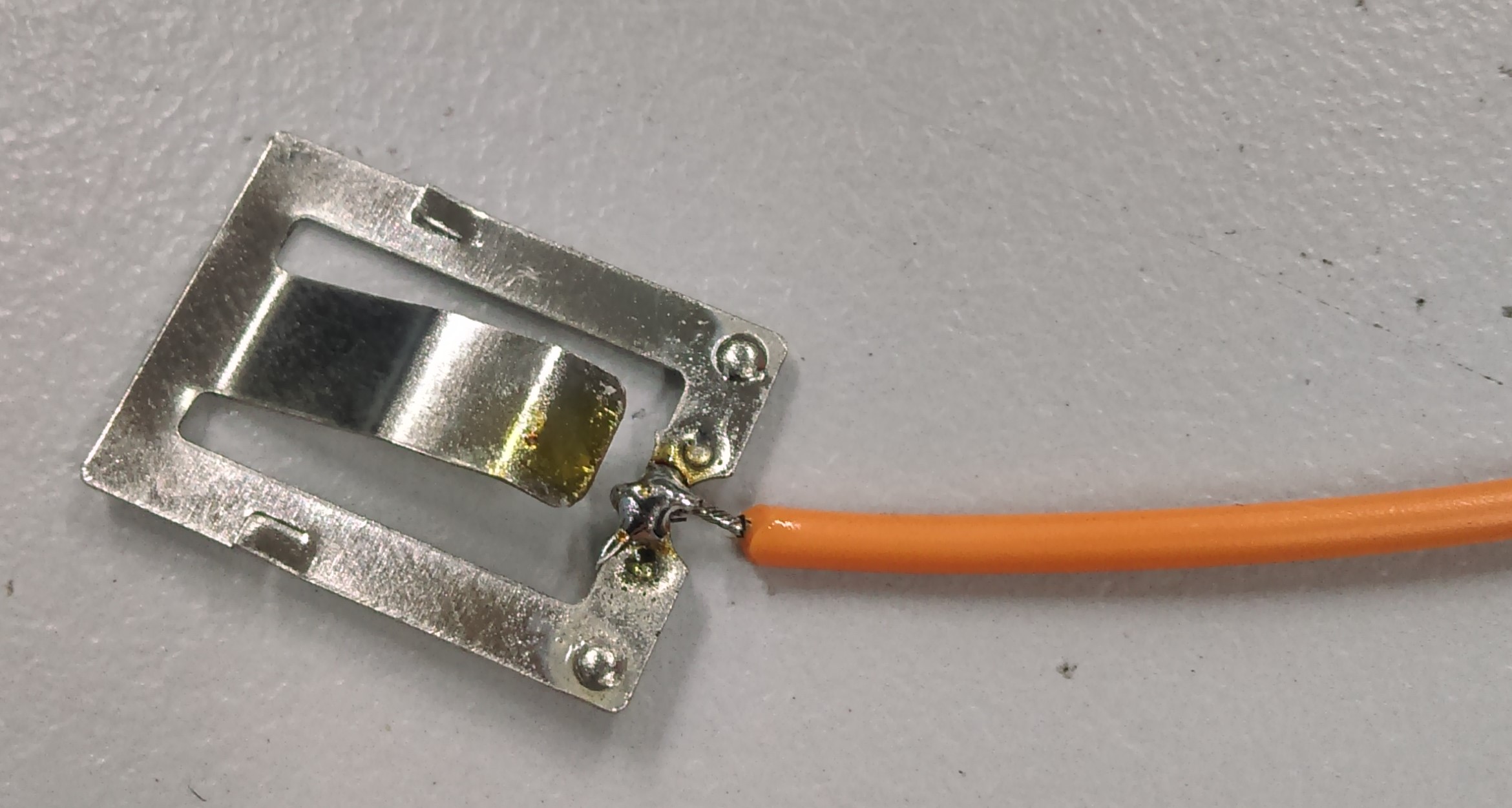
This part needs to be the most integral, and can be screwed onto the base of the battery holder (negative side.) unsolder the header connection on there and pull out the battery tab from the holder. you can unsolder the wire that's there and use a lead of an unused resistor (or otherwise) to make a solid solder connection going up from the battery base when you put it back in. this also makes a solid connection straight through the negative terminal of the sensor (do not solder until it's screwed in.)
Make sure that the screws do not affect the placement of the battery. you do have a thin margin of where you can put the screws, and keep them short. Using a hand drill like TD2089 (also mentioned in wifi meter project) is excellent for this.
Position the sensor so that the screw holes are on the thickest part of the plastic and drill, screw down and make sure it's strong.
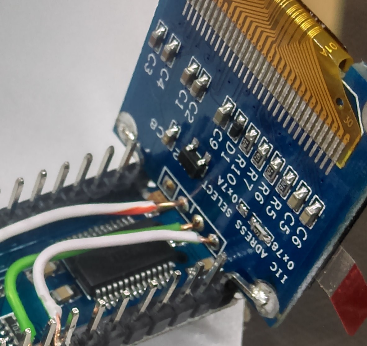
Unsolder the header on the OLED screen, be very careful with this, as if you leave the hot iron on it too long, the copper will remove and the device will become inoperable without forensic repair. A handy tip is to clip as much of the headers off as you can using a big pair of cutters, and pull the black plastic off which is holding them together.
Solder some solid core wire to VCC, SDA, and SCL pins, only about 2-3 inches are needed.
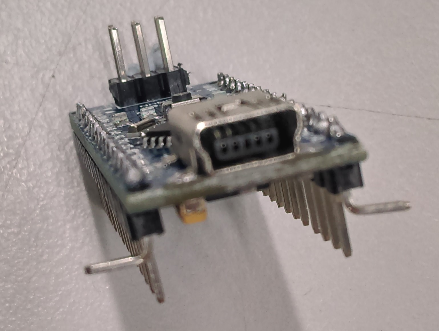
Bend the front two legs of the Nano (see picture) to make a sturdy holder for the OLED, place the OLED on the nano legs so that the top screw holes mount over the bent legs and the wires run along the underside of the Nano. (a 3rd hand is helpful for this.)
Solder the screwholes to the legs. use a short lead to go from GND up and over to the USB connection shell.
Trim and strip the wires so that they are just long enough to reach A4, A5, and ground solder in place.
The battery charger is just glued into place just above the moisture meter. Use the negative wire coming up from the moisture meter to connect to the negative terminal of the battery charger (BAT-)
The positive lead will go to the battery charger and one of the switch's side terminals. A small diagram can demonstrate the isolation of the USB, charger, and battery power:
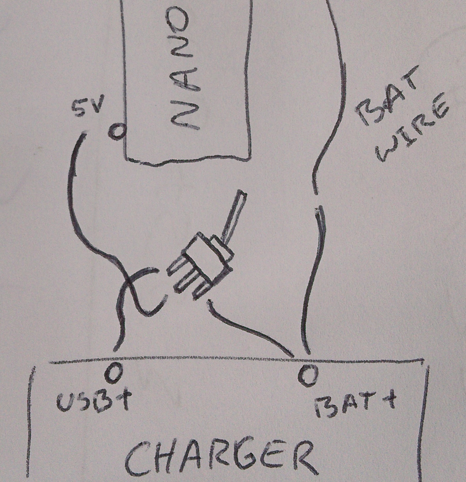
this switch changes between connecting battery power to 5V, and the charger input to 5V, allowing to both run or charge the battery. care is needed not to feed USB power directly into the battery however: using a blocking diode would have been ideal, but there was too much of a voltage drop on an already under-volt'd system
Glue the toggle switch in place just above the battery holder and solder the battery lead in place; you might have to trim it to size so there is not too much wire.
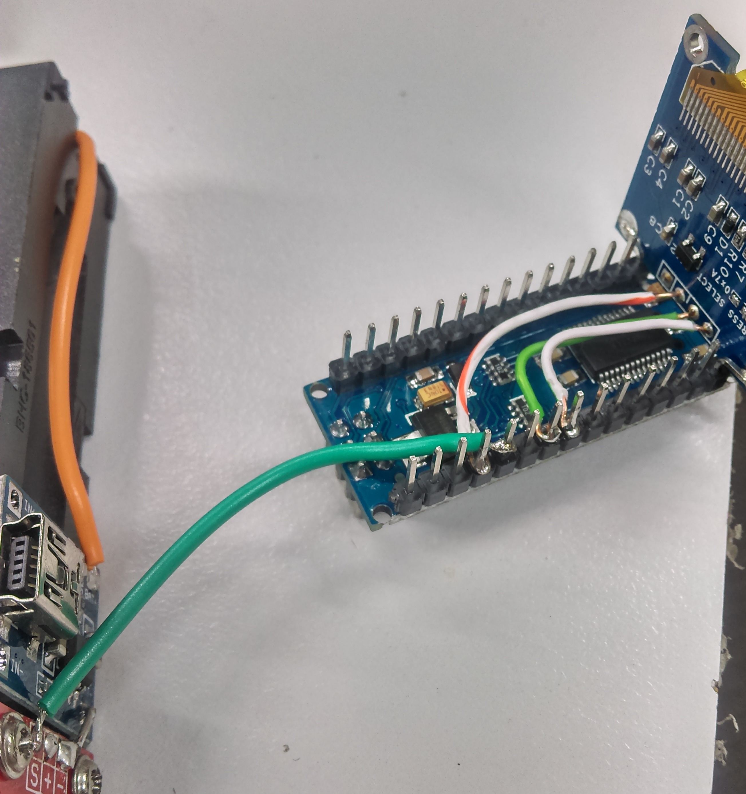
Now that you have a NANO with a screen, and the unit with battery charger, you can solder a short wire to go from S on the moisture sensor over to pin A6 on the NANO.
This picture is a picture of our first model, which did not include a switch and we made the sensor go to A7, but either A6/A7 is fine.
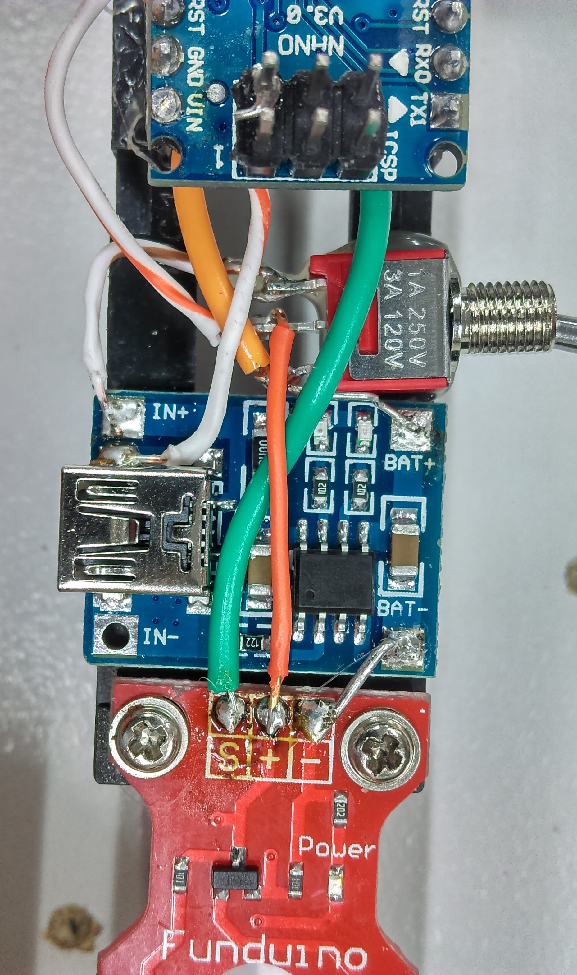
This project took a lot of do-over and revisions, you can see how dirty our project has become from soldering and unsoldering all the wires. once the switch is in place and the nano is glued onto the board, make the final connections between the switch, charger, and nano power connections. (also ensure the sensor is getting positive power aswel)
You can see how dirty our final model is here:
Be sure to get some Isoprop alcohol to clean the board properly before you present it as a present to someone.


